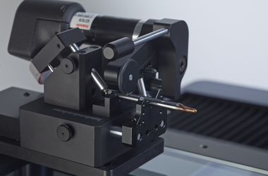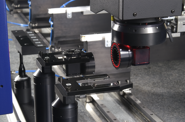


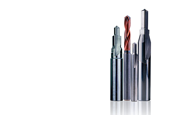
Step drills can be used, for example, to produce a through hole, a small blind hole and a chamfer in one machining step. The drill tip geometry depends on the material in which the bore is to be made. In addition to the drill tip geometry, the diameters of all steps, the core run, the taper, step lengths and step angles are measured. According to the application of the drill, the tolerances vary in the range of 5 µm to 20 µm and thus require a low to very low measurement uncertainty. The measuring time plays a subordinate role.
-
Applications
- 3D free-form workpieces
- Extruded workpieces
- Moulds
- Semiconductor workpieces
- Lithographic structures
- Metal-plastic composite workpieces
- Prismatic workpieces
- Stamped and bent parts
- Packaging
- Shaft-hub connections
- Shafts and axles
- Workpieces with micro-features
- Workpieces with optical functional surfaces
- Tools with geometrically defined cutting edges
- Tools with geometrically undefined cutting edges
- Gears
- Cylindrical workpieces
- Industries
- Products
- Service
- About Werth
- Careers
- Foundation
- Publications
- Downloads