Perfectly integrated multi-sensor systems: With the proven multi-ram concept, an even wider range of multi-sensor systems can now be used without restrictions and without time-consuming sensor changes. Each sensor has its own ram, the quills with non-active sensors are located in the park position outside the measuring range. One of the first users of the new device concept is the measuring services company Messtronik GmbH in the Black Forest. Quote from president Jörg Weißer: "As a measurement service provider, I receive a wide variety of workpieces. I use the multi-sensor systems on three independent sensor axes in combination with the rotary/tilt axis for measuring tasks that were previously considered too complex or even impossible to solve." The combined measuring ranges from 530 mm × 500 mm × 350 mm to 2130 mm × 1000 mm × 600 mm also enable multi-sensor systems to be used for larger workpieces.
All good things come in threes
The ScopeCheck® FB is probably the only coordinate measuring machine with three independent sensor axes for even greater flexibility. The machines allow fast measurements with high ease of use for three sensors, and even four sensors with the Werth Laser Probe integrated in the Werth Zoom or the Chromatic Focus Zoom (patents). The device family combines the benefits of conventional optical, tactile and multisensor coordinate measuring machines.
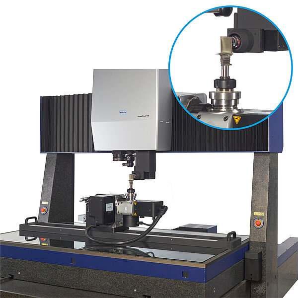
The widespread combination of coordinate measuring machine with image processing and stylus is achieved, for example, with a rotary/tilt head for tactile measurements from all orientations on the first and the Werth Multisensor System with Werth Zoom, Werth Laser Probe and the also patented Werth Contour Probe on the second ram. The patented Werth Fiber Probe® 3D or the Chromatic Focus Line sensor can then be used on the third ram. As the rotary/tilt head and the Werth Fiber Probe® 3D each require their own quill, such a combination is not possible by changing sensors on conventional machines with a single quill.
Optical, tactile and tactile-optical sensors can be used without changing sensors. Only one ram is positioned outside the measuring range and the required one is moved down. Combination with more specialised sensors such as the Werth Interferometer Probe for measurements in small bores is also possible.
This means that large and complex 3D workpieces as well as micro-structures can be measured. As an alternative to the rotary/tilt head, a slim probe quill allows collision-free measurement of geometries deep in the workpiece. If initially only a purely tactile machine is required, retrofitting to a multisensor coordinate measuring machine is also possible at a later date without restricting the application possibilities of the stylus.
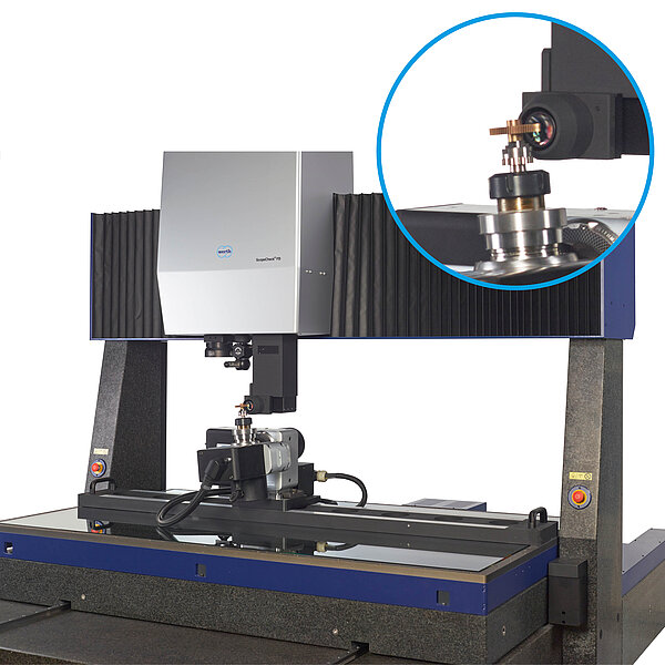
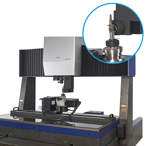
To ensure that the vertical CFL line is parallel to the gearing, the rotary axis is tilted from the vertical by the gearing angle (here about 20°) and then rotated 360° for gear measurements
Complete measurement of complex workpieces
When using multiple sensors, a rotary/tilt axis for the workpiece makes almost all geometric elements accessible to each sensor from different sides and can be measured in the same workpiece coordinate system. The user can mount the rotary/tilt axis on the machine in any orientation. The axis is then automatically calibrated and the run-out errors corrected. When using a rotary/tilt axis, three independent sensor axes are particularly advantageous due to the increased risk of collision.
In the configuration with rotary/tilt axis and Chromatic Focus Line sensor CFL, the ScopeCheck® FB enables the measurement of large gears with a diameter of 2 m, for example. The CFL line sensor is one of the sensors that have a preferred direction in which they function optimally. For gears with helical teeth, the CFL line should be parallel to the teeth. In the machine shown below, the angled CFL lenses point in the Y orientation, the CFL line is vertical. For the gear measurement, the tilt axis is mounted in the YZ plane. The rotary axis is tilted from the vertical by the gear angle, e.g. 20°, and then rotated by 360°. For example, to measure the spiral flutes of drills, the rotary axis can also be tilted in the X direction and rotated around the X axis.